| 5.1 Surround Sound |
The digital audio multichannel format developed by the Moving Picture Experts Group for digital soundtrack encoding for film, laserdiscs, videotapes, DVD, and HDTV broadcast. The designation “5.1” (first proposed by Tom Holman of THX fame) refers to the five discrete, full bandwidth (20-20kHz) channels – left, right, & center fronts, plus left & right surrounds – and the “.1” usually refers to the limited bandwidth (20-120Hz) subwoofer channel, but can also refer to a special effects/feature channel. Terminology used by both Dolby Digital and DTS Consumer (the home version of their theater Coherent Acoustics system). |
| Absorption |
The absorption of sound is the process by which sound energy is diminished when passing through a medium or when striking a surface. Sound molecules lose energy upon striking the material’s atoms, which become agitated, which we characterize as warmth; thus, absorption is literally the changing of sound energy to heat. A material’s ability to absorb sound is quantified by its absorption coefficient, whose value ranges between 0 (total reflection) and 1 (total absorption), and varies with sound frequency and the angle of incidence. |
| AC-3 (audio coding 3) |
Dolby’s digital audio data compression algorithm adopted for HDTV transmission and used in DVDs, laserdiscs and CDs for 5.1 multi-channel home theater use. |
| Active Crossover |
A loudspeaker crossover requiring power to operate. Usually rack-mounted as a separate unit, active crossovers require individual power amplifiers for each output frequency band. Available in configurations known as stereo 2-way, mono 3-way, etc. A stereo 2-way crossover is a two-channel unit that divides the incoming signal into two segments, labeled low and high outputs. A mono 3-way unit is a single channel device with 3 outputs, low, mid and high. In this case, the user sets two frequencies: the low-to-mid, and the mid-to-high crossover points. Up to stereo 5-way configurations exist for very elaborate systems. See also “Passive Crossover.” |
| Active Equalizer |
A variable equalizer requiring power to operate. Available in many different configurations and designs. Favored for low cost, small size, light weight, loading indifference, good isolation (high imput and low output impedances), gain availability (signal boosting possible), and line-driving ability. Disliked for increased noise performance, limited dynamic range, reduced reliability, and RFI susceptibility; however, used everywhere. |
| Active Subwoofer |
A component designed to amplify only bass frequencies, generally in a range of 50Hz and below. Active subwoofers are powered; they require connection to an AC wall socket. They use an interconnect cable terminated with RCA plugs or 15-pin DIN plugs to connect to the system amplifier. See also “Passive Subwoofer.” |
| ADAT (Alesis Digital Audio Tape) |
Digital tape recording system developed by Alesis, and since licensed to Fostex & Panasonic, putting 8-tracks of 16-bit, 44.1 kHz digital audio on S-VHS tape. |
| ADC (Analog to Digital Converter) |
The electronic component which converts the instantaneous value of an analog audio data through a single fiber optic cable. |
| Aero-PE
|
A proprietary dielectric material developed by TARA Labs and used as insulation in most TARA Labs cables.
Dielectric materials sound different because of the different rates that the materials store and release energy at different frequencies. PVC, a common dielectric material, causes distortion and coloration mostly audible in the mid-bass and mid-range frequencies, whereas Teflon® causes distortion in the upper treble frequencies, making coloration less noticeable.
TARA Labs uses a proprietary dielectric material called “Aerospace Polyethylene™” or “Aero-PE™.” This material is chemically treated to have low dielectric absorption and high dielectric elasticity. It reacts less with the signal in the conductor, making it more sonically neutral than other materials. Aero-PE is also extruded at a lower temperature than other insulating materials. Copper conductors insulated with Aero-PE are not exposed to high heat and therefore retain their specially annealed qualities. |
| AES/EBU interface |
The serial transmission format standardized for professional digital audio signals. |
Airtube™ Technology
 |
TARA Labs Airtube™ technology emerged from our determination to minimize dielectric content of cables and eliminate coloration. Featured in all RSC Air™ interconnects, Airtube technology is used to suspend conductors inside Teflon® tubes to prevent the adverse sonic effects caused by typical dielectric material, such as fiber or PVC. These materials absorb energy and release it back into the conductor out of phase with the audio signal, causing distortion and coloration in the highly audible mid-bass and mid-range frequencies. By removing dielectric materials that cause distortion and coloration, Airtube technology allows listeners to easily experience neutrality, transparency and a wonderfully detailed, spacious soundstage. |
| Amplitude |
The maximum absolute value reached by a voltage or current waveform. |
| Analog |
A real world physical quantity or data characterized by being continuously variable (rather than making discrete jumps), and can be as precise as the available measuring technique. |
| Audio |
Of or relating to humanly audible sound, i.e., audio is all the sounds that humans hear. |
| Balanced Line |
The IEEE dictionary defines a balanced circuit as “a circuit in which two branches are electrically alike and symmetrical with respect to a common reference point, usually ground.” This is the essence of a balanced interconnect. Namely, that two lines are driven equally and oppositely with respect to ground. Normally this also implies that the receiving circuits have matching impedances. Exactly matching impedances is preferred for it provides the best common mode rejection. Balances lines are the preferred method (for hum free) interconnecting of sound systems using a shielded twisted-pair. Because of its superior noise immunity, balanced lines also find use in interconnecting data signals, e.g., RS-422, and digital audio, e.g., AES/EBU. The principal behind balanced lines is that the signal is transmitted over one wire and received back on another wire. The shield does not carry any information, thus it is free to function as a true shield, but must be earth grounded at each end to be successful. [Long Answer: To understand why balanced lines are so successful, first examine a balanced, or differential (equivalent term) output stage, and then an input stage: A differential output stage simultaneously drives two lines, one positive and one negative. The voltage difference between these two wires is the audio signal. The two signals form an envelope that rides the wires to the balanced input stage. Note that the audio signal exists uniquely between these two lines — not between them and ground. The complete circuit path travels down on the positive line and back on the negative line. Ground is not needed to transmit the signal — this is the essence and power of balanced lines. Ground is used only for shielding and safety purposes. Conversely, an unbalanced line is one that transmits the audio signal between one wire and ground. The circuit path is down the wire and back through the shield cable connected to ground. Ground is the return path; the circuit does not work without it. A balanced (or differential) input stage extracts the difference between the two input lines, and that, of course, is the desired audio signal. It receives the envelope sent down the cable by the differential output. This circuit’s shining virtue is its great noise rejection ability. It has what is called great common-mode rejection. The concept here relies on induced noise showing up equally (or common) on each wire. It is mainly due to EMI (electromagnetic interference: passing through or near magnetic fields), RFI (radio frequency interference: strong broadcast signals), noisy ground references, or a combination of all three. The best balanced line designs have exactly equal impedance from each line relative to ground, guaranteeing equal noise susceptibility. Since the balanced input stage amplifies only the difference between the lines, it rejects everything else (noise) that is common to the lines.] |
Banana
 |
Type of connector commonly used on speaker cables. |
| Bandwidth |
The numerical difference between the upper and lower -3 dB points of a band of audio frequencies. Used to figure the Q, or quality factor, for a filter. |
| Bi-wirable
Bi-wired
Bi-wiring |
Refers to speakers that split the audio signal into two ranges: High-frequency and Low-frequency. These speakers have two pairs (four total) of speaker cable terminals, instead of the two terminals found on regular speakers. Bi-wiring provides the sonic advantage of physically separating high and low frequency runs, which results in improved high-frequency detail and integration of spatial cues.
Bi-wirable speakers can be connected either with two separate runs of regular speaker cable, or one run of speaker cable configured as “single run bi-wire.” Bi-wire cables, such as TARA Labs’ Prism Bi-Wire or RSC® Bi-wire speaker cables, have all necessary conductor runs contained within the same outer jacket. They provide the four connections necessary for bi-wirable speakers in a more convenient and attractive form.
Although bi-wiring results in improved definition and stereo separation, further improvement in the soundstage can be gained by TARA Labs’ unique range of bi-wire cables: RSC® 1800, RSC® Reference Bi-Wire, ISM Bi-Wire the Two and ISM Bi-Wire The One. In these very special cables, the bass conductors, positive and negative, are separately shielded to avoid electromagnetic radiation from the bass conductors affecting the high frequency conductors. This results in a very noticeable improvement in the smoothness of the entire sound field, producing a much less fatiguing sound. |
BNC
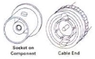 |
Type of connector used on digital cables and video cables. |
BSM
 |
Banana/Spade module. A speaker cable termination which is used with TARA Labs’ RSC® cables. BSM’s accept either a banana or a spade terminal. Male/female threads on the BSM’s and the connectors allow simple change from banana to spade, etc. |
| Capacitance |
The ability of conductors, separated by dielectrics, to store electrostatic charges. Interconnect cables should have capacitance figures of 24 pF or below. High capacitance cables produce sound which is rolled off – soft with a dulling of transients. |
| CAT 5 (Category 5 Cable) |
Unshielded twisted-pair (UTP) data grade cable (usually 24AWG). CAT 5 cable runs are limited to 100 meters (328 feet) due to signal radiation and attenuation considerations. Longer runs are vulnerable to electromechanical interference. CAT 5 cables are characterized to 100 MHz and support applications up to 100 Mbps. Most common application is 100Base-T Ethernet systems. |
| CATV |
A broadband transmission medium, most often using 75-ohm coaxial cable carrying many TV channels simultaneously. |
| CD (compact disc) |
Trademark term for the Sony-Philips digital audio optical disc storage system. The system stores 75 minutes (maximum) of digital audio and subcode information, or other non-audio data, on a 12-centimeter diameter optical disc. The disc is made of plastic, with a top metallized layer, and is read by reflected laser light. Variations (such as the 3″ disc) are reserved for special applications. |
| Ceralex™ |
A ceramic composite material developed for TARA Labs for the absorption of harmful RFI (Radio Frequency Interference). Ceralex components eliminate the effects of RFI, which include sonic distortion, noise, “snow,” and lack of image clarity. |
| Characteristic impedance
Impedance |
A measurement in co-axial cables determined by physical relationships between center conductor and shield. Not important at audio frequencies, very important for RF and digital transmissions. |
| CL-3 rating |
Refers to class 3 cables power-limited with a 300 volt rating. Laws or codes requiring use vary by state, but most require that any cables installed inside a wall be CL-3 rated. |
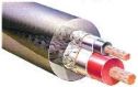
| Coaxial Cable |
A single copper conductor, surrounded with a heavy layer of insulation, covered by a thick surrounding copper shield and jacket. A constant-impedance unbalanced transmission line. |
| Component Video Connection |
A video system for color television that stores separate channels of red, green and blue. Becoming increasingly popular on DVD players, as well. A video signal split into 3 parts: luminance and two color signals (technically known as Y, B-Y, R-Y). Superior to S-video connection. |
| Composite |
A video signal combining luminance, chrominance, and synchronization data on a single coax cable using RCA connectors and color-coded yellow.The most common type of video connection. A composite video cable is a coaxial cable (such as the one used for most cable TV connections) with an RCA connector at each end. Composite video cables carry all color and sync functions in a single cable. Better quality alternatives are S-Video à Component Video à RGB à RGBS à RGBSS connections. |
| Conductor |
The part of the cable along which the signal travels. |
| DAC (Digital to Analog Converter) |
The electronic component which converts digital words into analog signals that can then be amplified and used to drive loudspeakers, etc. The DAC is the last link in the digital chain of signal processing. |
| DAT (Digital Audio Tape Recorder) |
A digital audio recorder utilizing a magnetic tape cassette system with rotary heads similar to that of a video recorder |
| Dielectric |
Insulating materials exposed to electric fields are called “dielectrics.” Dielectrics are necessary parts in the construction of any cable because they prevent oxidation and keep the conductors from touching one another. In audio cables, relatively low voltage and current levels mean that dielectric strength is not the most important factor. Far more significant in its effect on the sound is a material’s dielectric absorption. This characteristic describes the way a dielectric may discharge a secondary signal into the conductor out of phase with the audio signal.
As a current is passed through a conductor, an electromagnetic field is created which interacts with the dielectric material and temporarily displaces the molecular structure. If the dielectric material has good elasticity and can return quickly to its normal state, then the material is said to have low dielectric hysteresis or loss and will have little audible effect on the signal. |
| Digital |
Information represented by a sequence of ones and zeros. In digital transmission, analog signals are converted to signals of zeros or ones to be transmitted to a receiving site, interpreted, and used to reconstruct the original analog signal. |
| Digital Audio |
The use of sampling and quantization techniques to store or transmit audio information in binary form. The use of numbers (typically binary) to represent audio signals. |
| Distortion |
By its name you know it is a measure of unwanted signals. Distortion is the name given to anything that alters a pure input signal in any way other than changing its size. The most common forms of distortion are unwanted components or artifacts added to the original signal, including random and hum-related noise. Distortion measures a system’s linearity – or nonlinearity, whichever way you want to look at it. Anything unwanted added to the input signal changes its shape (skews, flattens, spikes, alters symmetry or asymmetry, even if these changes are microscopic, they are there). A spectral analysis of the output shows these unwanted components. If a piece of gear is perfect, it does not add distortion of any sort. The spectrum of the output shows only the original signal – nothing else – no added components, no added noise – nothing but the original signal. |
| Electromagnetic Flux |
The lines of force of magnetism which is developed by the passage of an electric current. Lines of force start at positive charges and end at negative charges. See The One™ Series Cables white paper for more information. |
| Fiber-Optic |
See Optical |
| Filter Network |
Some cable products use boxes attached to the cables that contain low-pass filter networks to filter RFI (Radio Frequency Interference) from the audio cables. These should not be confused with the Isolated Shield Matrix® products. The differences in both function and effectiveness are significant.
A filter network removes RFI from the audio signal by filtering out or rolling off all high frequency energy above a certain range. This affects a great deal of high frequency information at the upper end of the musical spectrum. Furthermore, these filter networks are connected directly in the signal path. When the signal is interrupted and fed through these low-pass filter networks, the cable’s electrical characteristics are changed to make a modified cable interface with limited and unnatural filter characteristics. The high frequency bandwidth is reduced. The audio band is affected also, as it is subjected by the filter network to rippling, and slower rise time (in the case of the Fourth-Order Bessel low-pass filter.) Furthermore, in a filter network RF inter-modulation has not been addressed properly because the heterodyning effect still affects the audio band. Additionally, the amplitude of the extreme high frequency harmonics of the music are filtered off, along with the RFI distortion, by generic capacitors and inductors in the filter network. The effects of a filter network are therefore subtractive, and ultimately color the original signal. |
| Floating Ground Station® |
The final link in the chain of the Isolated Shield Matrix, the Floating Ground Station®, is perhaps the most important. It is the most effective device ever conceived for the isolation and grounding of RFI (Radio Frequency Interference) because it functions completely outside of the signal path. Its function is to absorb RFI energy in the Isolated Floating Shield of the ISM cables independent of the system or any components of a system.
Inside the Floating Ground Station are Ceralex® components. Ceralex is a ceramic composite compound for the absorption and grounding of RFI and EMI. This compound is comprised of metallic oxides and a specific amalgam of mineral elements in a ceramic binder. |
| Frequency linearity
Linearity with Frequency |
Saying something is “linear” or “linear with frequency” means that the reproduced signal has the same ‘amplitude with frequency’ as the original signal. |
F-Type
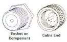 |
Type of connector sometimes used on video cables. Commonly used for Cable TV hook-up for RF video cables, such as antenna to TV/cable box, etc. |
| HD15 |
See VGA. |
| HDTV (High Definition Television) |
The standard for digital television in North America, still being revised. When finished will include a definition for picture quality at least that of a movie theater, or 35 mm slide, i.e., at least two million pixels (compared to 336,000 pixels for NTSC). |
| Heterodyning |
An effect caused by intermodulation of two or more signals, where additive and subtractive tones, known as beat frequencies, are created. For example, mixing two frequencies of 100 KHz and 1 KHz results in the following frequencies being created:
100 KHz
1 KHz
101 KHz
99 KHz
|
| High frequency |
Audio signal frequencies in the range of 1500 Hz to 20 KHz. Some examples of high-frequency tones are string instruments, cymbals, and some female vocals. |
| Impedance |
A measure of the complex resistive and reactive attributes of a component in an alternating-current (AC) circuit. Impedance is what restricts current flow in an AC electrical circuit; impedance is not relevant to DC circuits. In DC circuits, resistors limit current flow (because of their resistance). In AC circuits, inductors and capacitors similarly limit the AC current flow, but this is now because of their inductive or capacitive reactance. Impedance is like resistance but it is more. Impedance is the sum of a circuit, or device’s resistance AND reactance. Reactance is measured in ohms (like resistance and impedance) but is frequency-dependant. Think of impedance as the complete or total current limiting ohms of the circuit — the whole banana. Since AC circuits involve phase shift — i.e., the voltage and current are rarely in phase due to the storage effects (think “time;” it takes time to charge and discharge) of capacitors and inductors, the reactance is termed “complex,” that is there is a “real” part (resistive) and an “imaginary” part (bad terminology, but it means the phase shifting resistance part). To summarize: resistance has no phase shift; reactance (capacitors & inductors in AC circuits) includes phase shift; and impedance, is the sum of resistance and reactance. Just that simple. |
| Inductance |
Inductance in a wire (self inductance) is a measure of the result of current flow creating an electromagnetic field around the wire. As this is an alternating field, it induces voltage back into the wire, opposing current flow. Due to “skin effect” this become negligible at high frequencies. RSC™ is shaped to reduce the effects of inductance at all frequencies. |
| Intermodulation |
Interaction between two or more spontaneously produced signals. A situation to be avoided in audio or video signal transmission, as it generally results in some type of distortion. |
ISM Onboard Capsule™
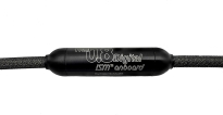 |
An advance in the technology that was applied in the design of The One™ and The 2™. The ISM OnBoard cables employ a capsule that is fitted directly to the cable. The ISM OnBoard capsule enables more effective control over RFI, as well as offering the advantages of a sleeker, more compact design and ease of connection. |
| Isolated Floating Shield™ |
This unique and proprietary shield design is central to the Isolated Shield Matrix®. Unlike conventional shields, which are connected to the cable at the load end, the Isolated Floating Shield floats at both ends. It is completely decoupled, both mechanically and electrically, from every component in the system, including the cables themselves.
This is an important distinction because it has a profound effect on lowering the amount of RF intermodulation that can be introduced into the system via the cables. TARA Labs’ in-house testing shows that the best of conventional shield designs are not effective at preventing RF intermodulation. The Isolated Shield Matrix, with its floating shield, dramatically reduces RF intermodulation of the audio signal.
In a typical interconnect the shield may prevent a certain amount of RF from modulating the signal through the conductors. But the shield is not deflecting RF energy in the environment – it is actually being absorbed. That energy is then returned to the system through the chassis of the component because the shield is coupled to the connector at one or both ends. By floating the shield at both ends, the Isolated Floating Shield avoids this problem. Energy absorbed by the shield is then transferred directly to the Floating Ground Station. |
| Isolated Shield Matrix® |
This technology, which is proprietary to TARA Labs, is the most effective system ever devised for the isolation of Radio Frequency Interference (RFI) from the audio signal.
The Isolated Shield Matrix system consists of three components: the interconnect cable itself (The One™, The 2™ and the ISM Digital cables), the Isolated Floating Shield, and a Floating Ground Station®. The purpose of the system is to provide an independent isolated absorption path for the transference of RFI and EMI without connection to the audio or video system. |
| L/R Channels |
The most common type of connection for carrying the audio signal from one component to the next. The audio signal is split into a Right and Left channel and carried by cables terminated with RCA connectors. |
| Line Multiplier |
Line multipliers, generally used with large screen or projection TVs, increase the number of lines in a standard TV picture, to reduce their visible effect. A line doubler (known as a scan converter) does not create any new lines, but displays the same lines twice as frequently. A line quadrupler displays three new lines for each one in the standard picture. Some line quadruplers “interpolate” new information by guessing the color and brightness information that should be in the new lines. A line quadrupler requires the use of a projector that has a scan frequency of at least 63 KHz. Near film quality images are possible with this technique. |
| Linearity with Frequency |
See “Frequency Linearity.” |
| Low frequency |
Audio signal frequencies in the range of 20 Hz to 150 Hz. Some examples of low-frequency tones are bass guitars, drums, and many movie sound effects. |
| Mid-range |
Audio signal frequencies in the range of 150 Hz to 1500 Hz. Some examples of mid-range tones are human voices, acoustic guitar and many woodwind instruments. |
| Multiple Solid Core Conductor Group |
Refers to a conductor that is made up of multiple solid-core conductors grouped together without insulation. Multiple conductors grouped together in this way will act as a single conductor, thereby increasing the current-carrying capability. However, depending on the configuration of the conductors within the group, this may be achieved with very little loss of high-frequency information. See “Trio Design™.” |
| Ohm |
A unit of electrical resistance equal to that of a conductor in which a current of one ampere is produced by a potential of one volt across its terminals. |
| Optical (Fiber-Optic) |
Many components (mostly CD or DVD players) have outputs in which the signal has been converted to modulated light. This light is carried from one component to another via a fiber-optic cable. The signal is then extracted in a reverse of the transmission. This method is immune to RF interference, and it will not cause hum loops. However, the quality of the electronics that convert signal to light and vice versa may affect the resulting sound. |
| Passive Crossover |
A loudspeaker crossover not requiring power for operation. Normally built into the loudspeaker cabinet. Passive crossovers do not require separate power amplifiers for each driver. |
| Passive Subwoofer |
A component designed to reproduce only bass frequencies, generally in a range of 80 Hz and below. Passive subwoofers do not have internal amplification or a connection to AC power. They use speaker wire and speaker cable terminals to connect to the system amplifier. See also “Active Subwoofer.” |
| Phone Jack |
Stereo ¼” connector consisting of tip (T), ring (R), and sleeve (S) sections, with T = left, R = right, and S = ground/shield. |
| Phono Jack |
Same as RCA. |
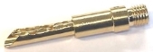
| Pin |
Type of connector used on speaker cables for use with speakers having spring-clip type terminals. |
Pressure Stranded™
 |
A proprietary technology introduced by TARA Labs that improves upon the performance and durability of typical stranded conductors. In typical stranded conductors, many strands of copper are bundled together to form a single conductor. The loose bundling results in air space between the strands. These air spaces will quickly produce points of oxidation, where the electrical AC signal can be modified and distorted. TARA Labs’ Pressure-Stranded™ conductors begin with soft annealed strands that are twisted together under tremendous force. The pressure results in more intimate contact between strands and elimination of the air spaces that cause oxidation. Pressure-Stranded conductors deliver a cleaner, clearer signal. Because they are not subject to oxidation, Pressure-Stranded conductors will perform better over time than typical stranded conductors, which will continue to oxidize, degrading signal transmission over the life of the cable. |
| Pressure-Fit™ RCA |
High contact pressure RCA plug. |
| Processor/Amp |
The component in a home theater system that receives audio and video signals from source components (DVD player, VCR, etc.) and sends them to the speakers and video display. |
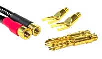
RCA
 |
Type of connector commonly used on interconnect cables, digital cables and video cables. |
Rectangular Solid Core®
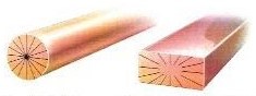 |
A solid, extruded conductor with a rectangular cross section. This technology is a TARA Labs exclusive.
Rectangular Solid Core® interconnects and speaker cables have become the reference standard for reviewers and serious audiophiles the world over due to their extremely accurate, neutral and frequency linear performance.
To understand the principle behind RSC® technology, it’s necessary to understand a phenomenon known as the “Skin Effect.” This principle states that in a round conductor higher frequencies will tend to travel towards the outside (or skin) or the conductor, while lower frequencies tend to be concentrated at the center of the conductor. The larger the diameter of a round conductor, the worse the effect will be, resulting in a significant roll-off of high frequencies in large gauge conductors.
Because of its rectangular cross section, an RSC conductor essentially has no center like a round conductor. Therefore it does not suffer the same high-frequency losses. It is the only conductor that is able to combine high current-carrying capability with extreme frequency linearity across the musical spectrum. |
| RFI/EMI |
Radio Frequency Interference/Electromagnetic Interference. The most common causes of noise and interference in the transmission of both audio and video signals.
Electromagnetic interference (EMI) refers to energy that is radiated by devices such as audio/video components, which contain transformers, AC cables and other electronic components that generate electromagnetic fields. The radiation of this energy is the major source of electromagnetic interference in an audio system. EMI affects the audio signal, adding noise and hash and obscuring low level detail and ambient information.
Radio Frequency Interference (RFI) is actually a type of electromagnetic interference referring to signals within the radio frequency spectrum of 70 kHz and above.
The abundance of RF pollution in the environment has been compounded in recent years by the proliferation of appliances generating RF signals. Furthermore, digital technology in audio systems has exacerbated the problem because RF modulation of the transmission of digital information affects the audio signal also. For this reason separate Floating Ground Stations® for Analog and Digital Interconnects are provided.
In an audio or home theater system, the interfaces which are most vulnerable to RFI are the interconnect cables themselves, which tend to behave like antennae for RF signals. The order of magnitude between the audio signal in the cable and the RFI in the cable is close enough in both analog and digital signal transmission that it can be a serious problem. (NOTE: This problem does not generally exist in speaker cable because of its characteristic combination of high current and low impedance.) |
| Roll off
Rolled off |
Loss in transmission. A signal that is “rolled off” in a certain frequency range will have audible distortion. |
| RSC Air™ |
Interconnects in which Rectangular Solid Core® conductors are suspended within a Teflon® Airtube. (See Airtube™ Technology.) There is also a range of RSC Air™ speaker cables. |
| RSC Gen 1™ Conductors |
The original Rectangular Solid Core® conductor, which is approximately 0.4mm x 3.4mm in size and roughly equivalent to a 18 AWG round conductor. Still in use in RSC® Prime speaker cables. All other RSC cables now use Gen 2 conductors. See Rectangular Solid Core. |
| RSC Gen 2™ Conductors |
The Rectangular Solid Core® conductor now in use in most RSC® interconnects and speaker cables, which is approximately0.2mm x 0.6mm in size and roughly equivalent to a 24 AWG round conductor. See Rectangular Solid Core. |
| SACD (Super Audio CD) |
Also known as DSD® or Direct Stream Digital®, joint trademark of Sony and Philips for their proposal for the next generation CD-standard. Sony and Philips have split from the DVD ranks to jointly propose their own solution comprised of a 1-bit, 64-times oversampled direct-stream digital SACD format. The original SACD proposal was for a hybrid disc comprising two layers: a high density (HD) DSD layer in the middle, and a standard density CD layer at the bottom. The two layers are read from the same side of the disc; the CD laser reads the bottom reflective layer through the semi-transmissive HD layer, while the middle layer is read by the HD laser delivering high-quality, multichannel sound without sacrificing backward compatibility. The HD layer has three tracks: the innermost is for two-channel stereo; the middle is a six-channel mix; and the outer is for such additional information as liner notes, still images and video clips. Maximum playing time is 74 minutes. This proposal turned out to be too expensive, so the SACD first release is a single-layer SACD-only disc. |
| S/PDIF (Sony/Phillips Digital Interface Format) |
A consumer version of the AES3 (old AES/EBU) digital audio interconnection standard based on coaxial cable and RCA connectors. |
| SA-OF8N® Copper
|
Super Annealed – Oxygen Free Eight Nines Copper (SA-OF8N®) is the new standard in high-performance copper purity. Variances in copper purity will result in audible differences. It is generally accepted that a purer, more conductive material can be more accurate and revealing that a material that is less conductive. TARA Labs’ proprietary annealing process, known as Super Annealing (SA), along with Oxygen-Free Eight Nines Copper (99.999999% pure) creates a unique, long, unbroken crystal structure called a “Monocrystal™” which has exquisitely smooth and detailed transfer of frequencies over a very wide bandwidth. Additionally, this new “Monocrystal” eliminates the high-frequency distortion caused by the junctions or breaks between crystals in typical copper conductors. Acting like diodes, those junctions between crystals in normal copper would alter the flow of high-frequency AC, causing audible distortion. |
| SCART |
A type of combination audio/video connector. |
Shielding
 |
| Shielding is used to protect the signal conductors from RFI and EMI. Braided shield is good for EMI, and foil for RFI. Combinations (foil and braid) are used for long runs for RF cables.
TARA Labs exclusive Parallel Shielding System was formulated to “common” any electrical potential (EMI interference voltages) between shields in RSC® Master Gen 2 and RSC Air™ interconnects. Our parallel shields connected together act as a ‘star-ground’ for the shields and the RFI/EMI radiation. By commoning the electrical potential in the shields, a better 3-dimensional reproduction of the soundstage is achieved due to both channels having the same level of reduced background noise. Example: A preamp’s transformer often concentrates radiation more toward one channel of the interconnect pair. If there is no shield, RFI would be modulated with the audio signal, often making the high frequencies sound bright or grainy. When shielding is used this sonic glare is reduced. When the shields are commoned, the left and right channels’ bandwidth and EMI interference effects are far more equal channel to channel. The result is better imaging, spatial cues and a naturally quiet background. |
|
| Source Components |
Components which provide the program material for home theater and audio systems: DVD players, CD players, VCR’s, turntables, etc. |
Spade
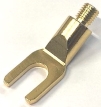 |
Type of connector commonly used on speaker cables. |
| Super Annealing™ |
The Super-Annealing process was developed by TARA Labs to improve the conductor’s ability to deliver a more neutral and transparent signal than ever before. Even the small differences in conductivity create audible differences in sound quality. Super-Annealing is a specialized metallurgical treatment that purifies and softens a conductor’s structure to lower it’s specific resistivity and dramatically increase the length and size of crystals in copper conductors.
The Super-Annealing process is performed in an oxygen-free environment to create an ultra-pure conductor with long-grain copper crystals. Traditional copper conductors are composed of much smaller crystals. The multiple breaks or junctions between these smaller crystals cause increased noise due to the diode effect of these junctions. They alter the flow of electrical signals and cause distortion. |
S-Video
 |
Also known as “Super VHS” and “Y/C video.” The S-Video signal is carried by two separately shielded conductors within a single jacket. The signal is split into chrominance (color) and luminance (brightness) information. S-Video generally provides a sharper, brighter picture with better color saturation than composite video. |
| Teflon® |
Teflon® is a registered trademark of DuPont Industries for its PTFE polymer. This polymer, or plastic material, is widely recognized as the least reactive dielectric material currently in use.
Insulating materials exposed to electric fields are called “dielectrics.” As a current is passed through a conductor, an electromagnetic field temporarily displaces the molecular structure of dielectric material. Fiber and PVC, common dielectrics, cause audible distortion and coloration. Teflon’s low dielectric absorption and superior molecular elasticity deliver a sonically neutral signal. |
| Torque-Lock™ RCA |
High contact locking RCA plug. |
| TosLink (Toshiba link) |
A popular consumer equipment fiber optic interface based upon the S/PDIF protocol, using an implementation first developed by Toshiba. |
| Trio-Design™ |
Refers to a multi solid-core conductor made up of three round conductors arranged in a trio, with no primary insulation between them. This unique design is used in Prism Series speaker cables. These cables have lower inductance than typical stranded or solid-core cables of the same gauge. Most conductors of a large gauge will roll off high frequencies due to the concentration of electromagnetic flux at the center of the conductor (see “Skin Effect”). Trio Design conductors have a space at the center, thereby reducing electromagnetic flux and the resultant roll-off of high frequencies. |
| Vacuum dielectric |
The type of dielectric used in TARA Labs’ top of the line interconnect, The Zero™. The Zero uses an extruded Teflon® tube with hollow galleries inside where the un-insulated RSC conductors are suspended. Air within the tube is then removed; creating a vacuum that surrounds the conductors.
A vacuum is the most effective dielectric environment possible, due to its lack of dielectric hysterisis (see “Dielectric.”) |
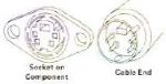
VGA
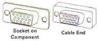 |
Also known as HD15. A type of video cable connection using a 15-pin plug similar to those used in computer connectors. |
XLR
 |
Type of connector used in balanced audio interconnects. Also used in AES/EBU digital interconnects, which are balanced and have a characteristic impedance of 110 ohm. |